
Measuring Tools
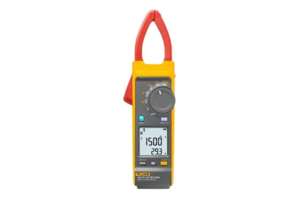
Fluke 393 Solar Clamp Meter CAT III 1500 V
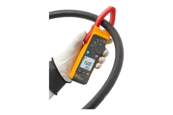
The Fluke 393 FC CAT III 1500 V True-rms Solar Clamp Meter with iFlex is designed for solar photovoltaic (PV) installation technicians and maintenance professionals who work in high voltage DC environments: PV arrays, wind power, electric railways, data centers battery banks for uninterruptible power supplies. The clamp meter will measure up to 1500 V DC and 1000 V AC with test leads, and up to 999.9 A DC or AC through the clamp jaw. The included iFlex flexible current probe extends AC current measurements up to 2500 A. The 393 has a thin jaw, giving you access to cables in crowded combiner boxes. Plus, the test leads are designed with your work in mind, and are also rated to CAT III 1500 V DC.
Key functions of the solar clamp meter:
- IP54 rated, ideal for work outdoors including PV panel testing
- DC power measurement, showing readings in kVA
- Audio Polarity indicator helps prevent accidental miswires
- Visual Continuity provides a bright green light in the display, ideal when working in dark and noisy environments
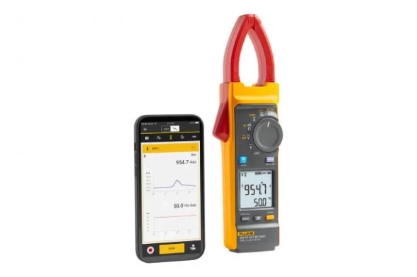
- Logging and reporting of test results via Fluke Connect software
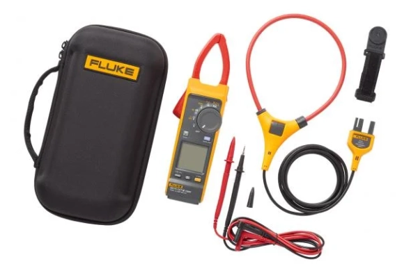
- When measuring ac current the included iFlex flexible current probe gives you unparalleled access to cable is tight spaces. The iFlex probe can be twisted through extremely small spaces and provide accurate current measurements.
The world's first CAT III 1500 V true-RMS solar clamp meter
Key functions of the solar clamp meter:
- IP54 rated, ideal for work outdoors including PV panel testing
- DC power measurement, showing readings in kVA
- Audio Polarity indicator helps prevent accidental miswires
- Visual Continuity provides a bright green light in the display, ideal when working in dark and noisy environments
- Logging and reporting of test results via Fluke Connect software
- When measuring ac current the included iFlex flexible current probe gives you unparalleled access to cable is tight spaces. The iFlex probe can be twisted through extremely small spaces and provide accurate current measurements.
The world's first CAT III 1500 V true-RMS solar clamp meter
Download
Products Lainnya
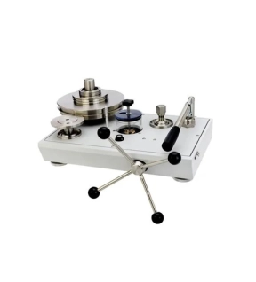
The P3100 models are available in single or dual piston format. Unit can be supplied in psi, bar, kgf/cm², and MPa. This robust instrument is highly accurate, quick and easy to use. Units feature a built-in priming pump for large volume applications, piston flotation indicators and a high quality screw press for fine pressure control.
Operating principle
Deadweight testers are the high performance pressure standards for pressure measurement. Utilizing the well proven piston-gauge system consisting of a vertically mounted, precision lapped piston and cylinder assembly, accurately calibrated weight masses (Force) are loaded on the piston (Area), which rises freely within its cylinder. These weights balance the upward force created by the pressure within the system. The pressure is measured when placed on a correctly spinning and floating piston. The total pressure measured is the summation of the weights plus the piston weight carrier assembly.
Instrument base
There are three basic variations in the hydraulic offering; single low pressure, single high pressure and dual piston models. Pressure is generated and controlled by means of a high quality screw press located on the front of the tester. A built-in hand pump is included as standard for all hydraulic models to prime the system and accommodate large volume requirements.
Piston/cylinder assemblies
The piston/cylinder assembly is the heart of each deadweight tester. They are manufactured from materials that provide stability, durability, and low thermal coefficients and distortion. Our experience and knowledge of piston/cylinder production and calibration ensure the precision and performance required for today’s demanding calibration requirements.
Weight masses
Standard weight masses are series 3 nonmagnetic austenitic stainless steel. Each mass is marked with the serial number of the instrument and the nominal pressure value relative to the high or low-pressure piston, when applicable. Optional fractional weights are stainless steel and/or solution heat treated aluminum.
Gravity correction
Gravity varies significantly with geographical location and this variation has a direct effect on the force of the weights and the accuracy of the deadweight tester. Each instrument can be calibrated to local gravity at no extra cost. If unspecified, instruments will be calibrated to Standard Gravity at 980.665 cm/s2.
Key features
• Pressure ranges to 60,000 psi (4000 bar)
• 0.015% of reading accuracy standard (0.008% optional)
• Single or dual piston format
• Built-in hand pumps standard
• Mounted spirit level with adjustable feet
• Units can be trimmed to local gravity FOC
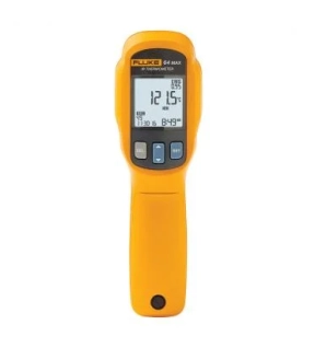
The Fluke 64 MAX thermometer has the precision you need to do the job accurately and won't exceed your budget. Designed and tested to withstand a drop of 3 meters, you can count on this compact and lightweight infrared thermometer to work when you need it in the harshest environments and when you can't get near it.
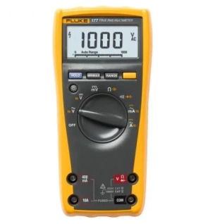
The three models of the new 170 Series are the new benchmark for common multimeters. All three set the standard with their combination of precision, features, ease of use, safety and reliability
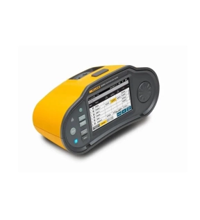
The Fluke 1670 Series Multifunction Installation Testers will revolutionize the way you work. With an ergonomic design, seamless user interface, integrated data management capabilities, wireless connectivity (1673 FC and 1674 FC), and comprehensive reporting software, the 1670 Series sets the new standard for an integrated installation testing solution.
Reliable installation testing is essential for ensuring the safety, optimal functionality, and integrity of a facility’s electrical systems. The 1670 Series' rugged design allows you to verify the safety of electrical installations in domestic, commercial, and industrial applications while meeting the requirements of IEC/HD 60364-6 and all relevant local installation test standards.
With the 1670 Series, you’ll be able to perform your required testing faster and reduce the time you spend on documentation, all while having the ultimate confidence in the data you’re collecting.
Simplified User Interface and Testing Setup
The 1670 Series takes data management to the next level streamlining test set up and preparation with an advanced bidirectional user interface. When setting up your project, the hierarchical tree topology for clients, sites, distribution boards, circuits, and test points can be easily customized using the high-resolution color touchscreen, or via TruTest™ desktop software. Edit, add, delete, or modify information directly on the tool as you test to ensure accurate data, or transfer updates to your tester via TruTest™ desktop software. Easy-to-read test tables help you quickly see that you are capturing the right measurement data at the right test point, every time. Now you can spend less time setting up your tester and organizing data, giving you more time to perform valuable testing.
Perform All Required Tests up to 30% Faster
Installation testing can be a time-consuming process. It often requires repetitive, manual test setups that can be frustrating and introduce the opportunity for errors.
The Fluke 1670 Series leverages a unique Auto Test function (1673 FC / 1674 FC) that enables you to run through an entire installation test sequence at the touch of a button. An integrated help function provides a visual connection guide to help ensure measurement success. Automatic measurement validation, with user-defined limit warnings, compares test results to the relevant standards and provides you with an immediate visual pass/fail indication to quickly identify potential issues. Eliminating manual testing and automating measurement validation means you can perform your tests up to 30% faster, giving you more time to focus on other critical tasks and increasing your productivity.
* 30% faster testing compared to manual testing.
Reduce Documentation and Reporting Time
The Fluke 1670 Series Multifunction Installation Testers help you reduce documentation time. Link test results to the circuit or point under test, reducing manual data entry and recordkeeping. You can also preview inspection results in the field via the tester and Fluke Connect™ compatibility making it easy to share your data from the field. Fluke TruTest™ Software lets you generate inspection certificates on site with just a few simple steps, so you can finalize and invoice your inspection at the time of service.
Insulation PreTest™ Functionality
The Fluke 1674 FC includes a patented Insulation PreTest™, so you can better protect the installation and avoid costly mistakes. If the tester detects that appliances are connected to the system during the test, it will stop the insulation test and provide a visual and audible warning. This helps eliminate accidental damage to peripheral equipment and saves you both time and money.
Optimized Software and Reporting
Fluke TruTest™ Software simplifies electrical system data management and reporting, eliminating the hassle of traditional data management with a single, integrated Fluke solution. Proper data management and testing information is critical for producing easy-to-understand reports for clients or your management team. TruTest™ streamlines the process by allowing you to create and transfer testing metadata between the software and your installation tester using a USB-C interface cable, or via the Fluke Connect mobile app, which helps you ensure accurate results.
The user-friendly interface, intuitive workflow, and report builder means that you can quickly format your measurement data into printable test certificates and reports, complete with your company logo and electronic signature. The live onscreen dashboard allows you to see the status of all your clients instantly and navigate to further levels of detail if desired.
Fluke TruTest Software allows you to create certificates that are compliant with a growing list of regional reports, including BS7671, DIN VDE 0100-600, ÖVE/ÖNORM E 8101, NIN/NIV, NEN3140, and other European installation test standards. All these reports are available at the touch of a button, and a pre-configured international template ensures that no matter your location, TruTest Software has you covered.
Fluke Connect™ Compatibility
The Fluke Connect™ mobile app allows you to download measurement data from your installation tester for later export to TruTest™ desktop software, allowing for prompt and effective reporting even while on location. Connect additional test tools, like the Fluke 369 FC Leakage Current Clamp or the Fluke 1630-2 FC Earth Ground Clamp to the 1673 FC and 1674 FC to synchronize data between auxiliary devices and test points, providing your clients with a clearer picture of overall facility health.
Additional Capabilities
• Field updatable — you can apply any changes to regulations or enhancements to the tester in the field.
• Compact and lightweight (less than 1.6 kg), with a padded neck strap to free your hands.
• Full-color touch screen and tactile rotary knob for fast navigation, with no complex multi-level menus.
• Rechargeable 2,500 mAh Li-ion battery to cover a full day of testing.
• Standard USB-C charging Port with fast charging support for convenient on-the-go charging.
• Newly designed professional hard case for transporting and protecting your installation tester and accessories.
• Additional high current loop mode for faster measurements than loop tests with non-trip mode for RCD protected circuits.
• Insulation Monitoring Devices (IMD) tests.
• Surge Protection Device (SPD) functional test.
• Voltage drop measurement function.
• Z Max memory for loop tests to support easy evaluation of the highest loop test value.
• Unique zero adapter for fast, reliable, and accurate test lead and mains cord compensation.
• Simultaneous readings of voltage measurements between L-N, L-PE, and N-PE using the mains cord. No need to change measurement connections.
• RCD trip current and trip time measurement in parallel (RCD type AC, A, B, F and GFCI).
• PEFC or PSC and loop impedance measurement in parallel, displays them together on the dual display.
• Ring testing lets you select the required input sockets without exchanging test leads.
• Continuity test with low test current (10 mA) to measure motor windings.
• Earth Volt Touchpad detects raised earth voltages > 50 V, indicating potentially dangerous situations.