a a a a a a a a a a a a
Distributor Fluke
Distributor Fluke
Customer Services
(021) 2908-5810
/
628111042805
Measuring Tools

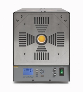
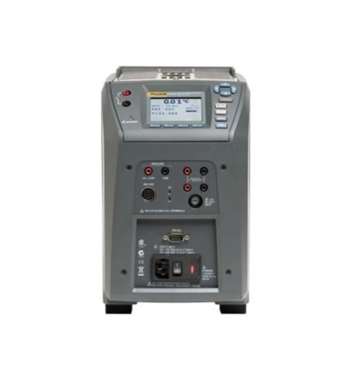
Fluke 9142 Field Metrology Well

Key features
• Lightweight, portable, and fast
• Built-in two-channel readout for PRT, RTD, thermocouple, 4-20 mA current
• True reference thermometry with accuracy to ±0.01 °C
• On-board automation and documentation
• Metrology performance in accuracy, stability, uniformity, and loading
Download
Produk Lainnya
124B Industrial ScopeMeter HandHeld Oscilloscope 40 MHz
Fluke 124B Industrial ScopeMeter Hand-Held Oscilloscope, 40 MHz
Fluke 124B Offers


Compact and rugged, this oscilloscope is ideal for industrial electrical and electro-mechanical equipment troubleshooting and maintenance applications. Features innovative functions that help technicians troubleshoot faster for quicker results and to keep their systems running smoothly. Additionally, triggering displays waveforms without having to adjust amplitude, timebase, and trigger settings.


Features

- Key measurements: Voltage and power waveforms

- Automatically capture, view and analyze complex waveforms: Fluke Connect and View™ triggering automatically displays waveforms without having to adjust amplitude, timebase and trigger settings, while Intellaset™ technology analyzes the signal and automatically displays critical numerical readings, making troubleshooting faster than ever

- View data locally on the instrument, or via Fluke Connect mobile app

- Dual-input digital oscilloscope and multimeter

- 40 MHz oscilloscope bandwidth

- Two 5000-count true-rms digital multimeters

- Connect-and-View trigger simplicity for hands-off operation

- IntellaSet technology automatically and intelligently adjusts numerical readout based on the measured signal

- Dual-input waveform and meter reading recorder for trending data over extended periods

- Recorder Event Detect captures elusive intermittent signals on repetitive waveforms up to 4 kHz

- Shielded test leads for oscilloscope, resistance and continuity measurements

- Resistance, continuity, diode and capacitance meter measurements

- Power measurements (W, VA, VAR, PF, DPF, Hz)

- Save or recall data and instrument setups

- Store instrument setups defined by a test sequence for routine maintenance or most often used test procedures

- External optically isolated USB interface to transfer, archive and analyze scope or meter data

- Optional WiFi adapter connected to internal USB port to wirelessly transfer information to the PC, laptop or Fluke Connect mobile app

- Rugged design to withstand 3 g Vibration, 30 g shock, and rated IP51 according to EN/IEC60529

- Highest safety rating in the industry: safety rated for CAT IV 600 V


Connect-and-View triggering for an instant, stable display


Oscilloscope users know how difficult triggering can be. Using the wrong settings can lead to unstable waveform captures, and sometimes the wrong measurement data. This instrument's unique Connect-andView triggering technology recognizes signal patterns and automatically sets up the correct triggering to provide a stable, reliable, and repeatable display. Connect-and-View triggering is designed to work with virtually any signal, including motor drives and control signals - without adjusting parameters, or even touching a button. Signal changes are instantly recognized and settings are automatically adjusted, providing a stable display even when measuring multiple test points in quick succession.


IntellaSet/AutoReading


The Auto Readings function with Fluke IntellaSet technology uses proprietary algorithms to intelligently analyze the measured waveform and automatically displays the most appropriate numerical measurements on the screen, so you can get the data you need easier than ever before. As an example, when the measured waveform is a line voltage signal, the Vrms and Hz readings are automatically displayed, whereas if the measured waveform is a square wave, the Vpeak-peak, and Hz readings are automatically displayed. Using IntellaSet technology in conjunction with Connect-and-View automatic triggering you can be sure you're seeing not only the correct waveform but the appropriate numerical reading as well. All without touching a button.


Industrial equipment needs a reliable power supply to operate properly, use the dual input to obtain key power measurements


For single-phase or 3-phase balanced systems, the dual inputs of the Industrial ScopeMeter 120B Series can measure AC+DC RMS voltage on channel A and AC+DC RMS current on channel B. This oscilloscope can then calculate; frequency, phase angle, active power (kW), reactive power (VA or var), power factor (PF), or displacement power factor (DPF) and can also calculate the power values for a 3-phase system where all phases have equal voltage and currents. This applies to both balanced systems and resistive loads.


One test lead to measure multiple electrical parameters


High-frequency waveform, meter, capacitance, and resistance measurements as well as continuity checks are all covered by a single set of shielded test leads. No time is wasted finding or swapping leads.


Fluke Connect mobile app compatibility


Automated industrial machinery is harder than ever to troubleshoot. It's not enough to just know where you have to test, you also have to know what to look for and that can be hard without baseline measurement data or access to subject matter experts. This Fluke Connect Assets wireless system of software and wireless test tools enables technicians to reduce maintenance costs and increase uptime with accurate equipment records and maintenance data that is easy to interpret, and share. Compare and contrast test point measurement data and trends so you can better understand signal characteristics and changes over time. And, by storing maintenance data on the Fluke Cloud you can enable team members to access it from wherever and whenever they need to so you can get advice or approvals in the field and get your systems up and running faster than ever before.


Use the comprehensive recorder modes to help find intermittent faults with ease


The toughest faults to find are those that happen only once in a while-intermittent event. They can be caused by bad connections, dust, dirt, corrosion, or simply broken wiring or connectors. Other factors, like line outages and sags or the starting and stopping of a motor, can also cause intermittent events resulting in equipment shutdowns. When these events happen, you may not be around to see them. But, your Fluke ScopeMeter Test Tool will. You can either plot the minimum and maximum peak measurement values or record the waveform trace. And, with expandable micro SD memory, recording sessions can be done for up to 14 days. This recorder is even more powerful with the addition of Recorder Event Detect, which makes detecting and logging intermittent faults easier than ever. Just set a threshold on a meter reading or scope trace and deviations are tagged as unique events. You no longer need to search through masses of data to pinpoint faults, and can quickly step from one tagged event to the next, while still having access to the full data
MDA550 Series III Motor Drive Analyzer
Fluke MDA-550 Series III Motor Drive Analyzer
Simplify complex motor drive troubleshooting with guided test setups and automatic drive measurement that provide reliable, repeatable test results.

The Fluke MDA 550 Motor-Drive Analyzer saves time and the hassle of setting up complex measurements, and simplifies the troubleshooting process. Simply select a step-by-step guided test and measurement will show you where to make voltage and current connections, while preset measurement profiles ensure you will get all the data you need for every critical motor drive part, from input to output, the DC bus, and the motor itself . Doing simple to complex measurements? MDA-550 can do it. What's more, making reports before (as-found) and after (as-left) repairs or adjustments becomes more practical. This is all thanks to its built-in report generator feature.


The MDA-550 is an ideal portable motor drive analysis testing tool. Not only that, this tool can also be used to safely detect and solve common problems in inverter-type motor drive systems.


- Measures main motor drive parameters , including voltage, current, DC bus voltage level and AC ripple, voltage and current unbalance and harmonics, voltage modulation, and motor shaft voltage discharge.

- Performs broader harmonic measurements to identify the impact of low and high order harmonics on your power system.

- Performs guided measurements of motor drive input, DC bus, drive output, motor input, and shaft measurements with step-by-step graphical diagrams of voltage and current connections.

- Uses simple measurement settings with preset measurement profiles to automatically trigger data collection based on the selected test procedure.

- Quickly and easily generate reports that are perfect for documenting problem solving and collaborative work with others.

- Measure additional electrical parameters with a complete 500 MHz oscilloscope, meter and logger capability for a wide range of electrical and electronic measurements in industrial systems


The Fluke MDA-550 Motor Drive Analyzer uses guided test measurements to make analysis even easier


Drive input


Quickly measure input voltage and current to see if values ??are within acceptable limits by comparing the rated voltage to the actual supply voltage. It then checks the input current to determine if the current is within its maximum rating and the conductor size is appropriate. You can also check if the harmonic distortion is within an acceptable level. There are two options for doing this: carefully examine the shape of the waveform or look at the harmonics spectrum screen which displays total harmonic distortion and individual harmonics.


Imbalance of voltage and current


Check the voltage unbalance at the input terminals so you can make sure the voltage unbalance is not too high (> 6-8%), and the phase rotation is correct. You can also check for current unbalance, as too large an imbalance can indicate a driving rectifier problem.


Wider harmonic measurement


Excess harmonics are not only a threat to your rotating machine, but also to other equipment connected to the mains power system. As well as being able to detect motor drive harmonics, the MDA-550 can also detect the potential impact of inverter switching electronics. The MDA-550 has three harmonic ranges, 1st to 51st harmonics, 1 to 9 kHz, and 9 kHz to 150 kHz providing the ability to detect harmonic pollution problems.


Bus DC


In motor drives, the conversion of AC to DC inside the drive is very important. The reason is that for the best drive performance it is necessary to have the right voltage and adequate smoothing with low ripple. High ripple voltages can be an indicator of a faulty capacitor or a faulty motor connected. The logging function can be used to dynamically check the performance of the DC bus in operating mode when load is applied.


Drive output


Check drive output focusing on voltage to frequency (V/F) ratio, and voltage modulation. If the V/F ratio is high, the motor may overheat. With a low V/F ratio, the connected motor may not be able to provide the torque required at the load to carry out the process for which it is intended.


Voltage modulation


Pulse Width Modulation signal measurements are used to check for high voltage peaks that can damage motor winding insulation. The rise time or steepness of the impulse is indicated by a dV/dt reading (value of change in voltage over time), this must be compared with the specified motor insulation. Metering can also be used to measure switching frequency. Its purpose is to detect whether there is a potential problem with the switching electronics, or with grounding, as the signal drifts up and down.


Input Motor


Ensuring the supply of voltage at the motor input terminal is important. However, choosing a connecting cable between the drive and the motor is no less important. Incorrect cable selection can cause damage to the drive and motor due to overvoltage peaks. Checking that the current at the terminals is within the motor's rating is critical because excess current can cause the motor to overheat, reducing the life of the stator insulation which can cause premature failure of the motor.


Motor shaft voltage


The voltage impulse in the variable speed drive is generated from the circuit between the motor stator and the rotor until a voltage appears on the rotor shaft. If the rotor shaft voltage exceeds the insulating capacity of the bearing grease, flashover currents (glow) may occur. As a result, pitting and fluting of the motor bearing rotation occurs, namely damage that causes the motor to fail prematurely. The MDA-550 is equipped with a carbon fiber brushed probe tip that makes it easy for you to detect destructive flashover currents. Meanwhile, the amplitude of the impulse and the number of events can be used as a consideration in taking preventive action. With the addition of these accessories and capabilities, you can spot potential faults without the need to buy expensive permanent solutions.


Step-by-step guided measurements ensure you have the data you need, when you need it


The MDA-550 is designed to help you quickly and easily test and troubleshoot common three-phase and single-phase inverter-type motor drive systems. Onscreen information and a step-by-step setup guide make it easy for you to configure the analyzer. Not only that, the information and guide will also provide the required drive measurements. That way, you can quickly make informed decisions regarding maintenance. From power input to attached motor, the MDA-550 provides measurement capabilities for the fastest motor drive solutions.
754 Documenting Process CalibratorHART
Fluke 754 Documenting Process Calibrator-HART
Portable multi-function calibrator simplifies calibration work


Whether you're calibrating instruments, troubleshooting a problem, or running routine maintenance, the Fluke 754 with HART® communication can help you get the job done faster. It does many different tasks quickly and it's the only process calibrator you need to carry. This rugged, reliable, integrated communicating calibrator is ideal for calibrating, maintaining, and troubleshooting HART smart transmitters and other instrumentation.


Measurement and source capabilities:

- AC/DC voltage

- mA loop w/ 24V loop power

- Pressure

- Thermocouples & RTDs

- Frequency

- Resistance


Enhanced process calibrator operation


With the bright white dual display, you’ll be able to read both sourced and measured parameters simultaneously. The rechargeable Li-Ion battery offers up to 10 hours uninterrupted usage allowing you to complete one task after another without needing to stop, and also includes direct AC power capabilities if needed. Finally, communicate with HART smart digital transmitters directly through the mA measurement jacks for seamless calibration with fewer connections.


Do more, with less

The 754 does the work of several tools. It sources, simulates and measures pressure, temperature, and electrical signals with one rugged, hand-held device. The powerful built-in HART interface can perform nearly all day-to-day tasks you now perform with a separate digital communicator. It can handle fast-pulsed RTD transmitters and PLCs, with pulses as short as 1 ms. The 754 also measures/sources pressure using any of the Fluke 750P Series Pressure Modules as a reference and boasts many additional features like:

- Custom auto-step and ramping

- Custom units

- User-entered values during test

- One-point and two-point switch testing

- Square root DP flow testing

- Programmable measurement delay


Download procedures, lists, and instructions


The 754 is a power multifunction documenting calibrator that you can use to download procedures, lists, and instructions created with software, or upload data for printing, archiving, and analysis. The tool can hold up to a full week of downloaded procedures and calibration results and offers compatibility with many asset management software. Users can also create and run automated as-found or as-left procedures to satisfy quality programs or regulations, and records and documents results.


For documentation, the 754 automates calibration procedures and captures your data. And, of course, it helps you meet rigorous standards like ISO 9000, FDA, EPA, and OSHA regulations. Plus, the graphical screen, Li-Ion battery for longer life, USB port, and accessories help you work smarter and faster.


To create a seamless/paperless calibration management system consider adding Fluke DPCTrack2 Calibration Management software.
404E406E405408410 Laser Distance Meter
Fluke 404E/406E/405/408/410 Laser Distance Meter
- Quickly measure distance, calculate area / volume / pythagoras

- Auto level and height

- Built to withstand rainy or dusty conditions: 1-meter drop tested with rated IP54 (Fluke 404E / 406E), IP65 (Fluke 405 / 408 / 410),

- Electronic angle display, auxiliary level measurement

- Up to 100 sets of data storage

- The battery life up to 5000 single measurements Automatically power off after 3 minutes of inactivity


Fluke 405 / 408 / 410 provide additional features as :

- Universal tripod interface, easy to use

- Type-C charging port, strong endurance

- 2-inch HD display, clear viewing in full sunlight