
Measuring Tools
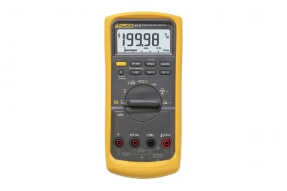
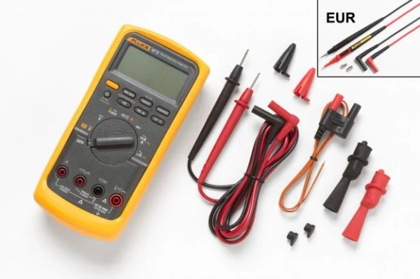
Fluke 87V Industrial Multimeter
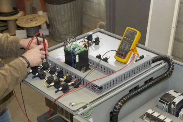
From the control room to the factory floor, the Fluke 80 Series digital multimeter has earned a reputation as the digital multimeter that industrial technicians trust. When productivity suffers, the Fluke 80 Series provides the accuracy and advanced troubleshooting capabilities you need to solve problems fast.
Use the low pass filter function to accurately measure voltage and frequency on electrically noisy equipment such as variable speed motor drives. Use the peak capture function to detect occasional faults and switch as fast as 250 microseconds (µs).
And work with confidence. The Input Alert function provides an audio alert against misuse of the input plug. The Fluke 80 Series multimeters have been tested separately for use in CAT IV 600 V/CAT III 1000 V environments. The Series can withstand impulses in excess of 8000 V and reduce the risks associated with surges and surges.
At Fluke, our ideas come straight from the workplace. We work with users like you to build test kits that do the job you want them to do for as long as you need them—and give you full value. We design and manufacture the Fluke 80 Series multimeters in the U.S.A. The 80 Series is backed by a limited lifetime warranty. And we back it with a limited lifetime warranty so you can work smarter, faster, and safer.
Download
Produk Lainnya
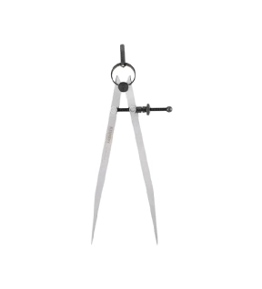
Kennedy 8" SPRING TYPE DIVIDERS-SOLID NUT
Manufactured from high quality polished steel. Ground finished points, a fine adjusting screw is mounted across the legs for setting the distance between the two points. A circular spring bow joins the legs, with a knurled extension attached for use when pivoting the dividers. Dividers are used for scribing arcs and circles, a light centre punch mark on the work keeps the pivot leg in the centre while marking.
Features and Benefits
• High quality polished steel with ground finished points
• Adjusting screw mounted across the legs for setting distance between points
• A light centre punch mark on the work keeps pivot leg in the centre while marking
• Ideal for use in scribing arcs and circle applications
Features and Benefits
• High quality polished steel with ground finished points
• Adjusting screw mounted across the legs for setting distance between points
• A light centre punch mark on the work keeps pivot leg in the centre while marking
• Ideal for use in scribing arcs and circle applications
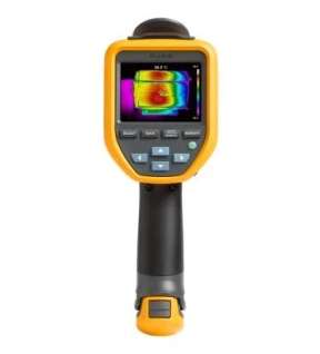
Fluke TiS55+ Thermal Camera
Strong. reliable. Accurate At Fluke, we know accidents happen, tools that are dropped, kicked, stepped on, or bumped. You do not have to change the tool if it falls off the workbench or is splashed with water or dirt. That's why we designed the TiS55+ thermal camera to withstand drops from a height of 2 meters and is water/dust resistant (IP54). You need to know that your camera is ready to use at all times.
No need for a clipboard
With so many inspections in one day, it can be difficult to remember what you saw and where it was. Maybe you brought a clipboard with you to take notes. The TiS55+ comes with a built-in personal assistant, which means you can get rid of the clipboard and have all the information you need in the pictures you take, including:
- Voice notes
Records up to 60 seconds per thermal image
Identify exactly what you see in realtime
- IR-PhotoNotes
Take a photo of the asset number and other identifiers
Use as a reference when viewing thermal images on your computer
- Asset Tagging
Sort your images by assets
Scan the QR code on your asset and start taking thermal images
Connect your camera to your computer to view images, sorted by asset
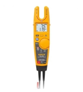
Fluke T6-1000 Electrical Tester
• Measure voltage to 1000 V AC without test leads
• Simultaneously measure voltage and current
• 17.8 mm open fork is widest in the industry
• Measure up to 200 A on 4/0 wires (120 mm2)
• Simultaneously measure voltage and current
• 17.8 mm open fork is widest in the industry
• Measure up to 200 A on 4/0 wires (120 mm2)
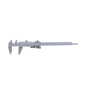
Kennedy 7"/180mm VERNIER CALIPER
Metric & Inch Reading - Graduation: 0.02mm/0.001"
Incorporating Quadri feature - gives outside, inside, depth and step readings.
Fine adjustment feature allows improved sensitivity of slider movement.
14° vernier face angle reduces parallax.
Satin chrome finish with clear easy read graduations.
Incorporating Quadri feature - gives outside, inside, depth and step readings.
Fine adjustment feature allows improved sensitivity of slider movement.
14° vernier face angle reduces parallax.
Satin chrome finish with clear easy read graduations.


