Measuring Tools
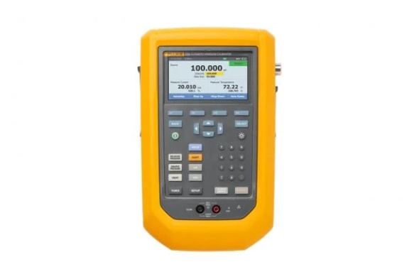
Fluke 729 Automatic Pressure Calibrator
Automatically generates and controls pressure up to 300 psi (20 bar, 2 MPa). Enter the pressure and the 729 will automatically pump to the desired pressure. Fill out the test template and the 729 will automatically pump and document pressure calibration tests at multiple points.
Easy calibration documentation using predefined templates for transmitters and switches. Enter the initial and final test pressures and the number of test points. The rest of the 729 did by documenting the applied pressure, the measured mA, and the % error of each test point. The bright color graphics display will highlight the tolerance test results in red.
Automatic fine adjustment of internal pressure helps compensate for minor leaks in hoses and test settings. There is no need to manually turn the vernier to check for leaks, helping to eliminate the hassle of manual pumping and manual fine adjustment of test settings.
HART communication allows trimming of mA output, trimming to applied value, and trimming to zero pressure from HART pressure transmitters. You can also perform light configuration tasks such as changing transmitter tags, units of measurement, and setting ranges. Other supported HART commands include setting a fixed mA output for troubleshooting, reading device configurations and variables, and reading device diagnostics.
Measures mA signal at transmitter source output and simulates mA signal for testing I/Ps and other mA loop devices. Includes a 24V loop power supply to test and power transmitters in self-tests not connected to a control system.
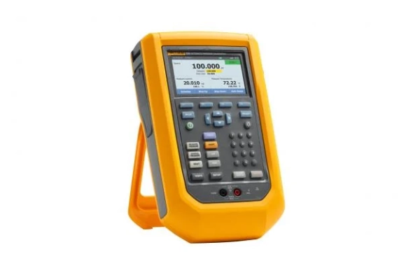
Rugged portable case design 3 year warranty sets the 729 apart from most other pressure calibrators. The 729 is tested and guaranteed to withstand a 1 meter drop test, making it ready for field instrumentation calibration work.
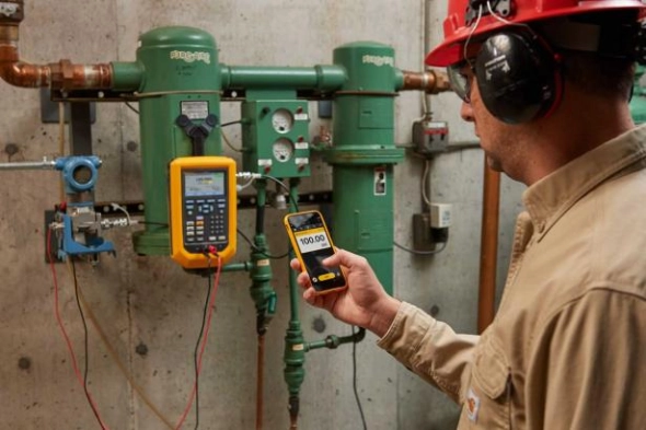
Fluke Connect® compatibility allows users to remotely monitor using the Fluke Connect mobile app as well as manage and store pressure measurements and log events. Share measurements using ShareLive™ video calls and email.
Measure temperature with the optional 720RTD probe to perform resistance transfer calibration.
Measure pressure with the old 700 Series and new 750 Series pressure modules if a different pressure measurement range or resolution is desired.
Multiple language support : select the language from the instrument setup utility. Hart communication commands are limited to English per HART device description and protocol.
The rigid yet flexible carrying case is designed for field work, with room in the bag for storing, test hoses, fittings, test cables and small tools needed for field pressure calibration.
Portable automatic pressure calibrator makes pressure calibration easy
The Fluke 729 Automatic Pressure Calibrator has been specifically designed with the work of process technicians in mind to simplify the pressure calibration process and provide faster, more accurate test results. Technicians know that calibrating pressure is a time-consuming task, but the 729 makes it easier than ever with an internal electric pump that generates and adjusts pressure automatically in a rugged, easy-to-use portable package.
The 729's ideal portable pressure calibrator, allows you to simply enter a target pressure, and the calibrator will pump automatically at the desired set point. Then, an internal fine adjustment control automatically stabilizes the pressure at the set value.
The Fluke 729 can also test multiple pressure test points automatically and automatically document the results. Calibration is as simple as entering the initial and final pressures as well as the number of test points and tolerance levels. The remaining 729 do.
Built-in HART communication capability allows for mA tuning of HART transmitters, lightweight HART configuration, and the ability to adjust to applied 0% and 100% values.
Upload and manage documented calibration results with DPCTrack2™ Calibration Management Software, making it easier to manage your instrumentation, create scheduled tests and reports, and manage calibration data.
With three selectable ranges, 30 psi (2 bar, 200 kPa), 150 psi (10 bar, 1 MPa), and 300 psi (20 bar, 2 MPa), the Fluke 729 Automatic Pressure Calibrator is designed to work anytime, anywhere. wherever you need it.
30 psi range, 2 bar, no wireless communication
Easy calibration documentation using predefined templates for transmitters and switches. Enter the initial and final test pressures and the number of test points. The rest of the 729 did by documenting the applied pressure, the measured mA, and the % error of each test point. The bright color graphics display will highlight the tolerance test results in red.
Automatic fine adjustment of internal pressure helps compensate for minor leaks in hoses and test settings. There is no need to manually turn the vernier to check for leaks, helping to eliminate the hassle of manual pumping and manual fine adjustment of test settings.
HART communication allows trimming of mA output, trimming to applied value, and trimming to zero pressure from HART pressure transmitters. You can also perform light configuration tasks such as changing transmitter tags, units of measurement, and setting ranges. Other supported HART commands include setting a fixed mA output for troubleshooting, reading device configurations and variables, and reading device diagnostics.
Measures mA signal at transmitter source output and simulates mA signal for testing I/Ps and other mA loop devices. Includes a 24V loop power supply to test and power transmitters in self-tests not connected to a control system.
Rugged portable case design 3 year warranty sets the 729 apart from most other pressure calibrators. The 729 is tested and guaranteed to withstand a 1 meter drop test, making it ready for field instrumentation calibration work.
Fluke Connect® compatibility allows users to remotely monitor using the Fluke Connect mobile app as well as manage and store pressure measurements and log events. Share measurements using ShareLive™ video calls and email.
Measure temperature with the optional 720RTD probe to perform resistance transfer calibration.
Measure pressure with the old 700 Series and new 750 Series pressure modules if a different pressure measurement range or resolution is desired.
Multiple language support : select the language from the instrument setup utility. Hart communication commands are limited to English per HART device description and protocol.
The rigid yet flexible carrying case is designed for field work, with room in the bag for storing, test hoses, fittings, test cables and small tools needed for field pressure calibration.
Portable automatic pressure calibrator makes pressure calibration easy
The Fluke 729 Automatic Pressure Calibrator has been specifically designed with the work of process technicians in mind to simplify the pressure calibration process and provide faster, more accurate test results. Technicians know that calibrating pressure is a time-consuming task, but the 729 makes it easier than ever with an internal electric pump that generates and adjusts pressure automatically in a rugged, easy-to-use portable package.
The 729's ideal portable pressure calibrator, allows you to simply enter a target pressure, and the calibrator will pump automatically at the desired set point. Then, an internal fine adjustment control automatically stabilizes the pressure at the set value.
The Fluke 729 can also test multiple pressure test points automatically and automatically document the results. Calibration is as simple as entering the initial and final pressures as well as the number of test points and tolerance levels. The remaining 729 do.
Built-in HART communication capability allows for mA tuning of HART transmitters, lightweight HART configuration, and the ability to adjust to applied 0% and 100% values.
Upload and manage documented calibration results with DPCTrack2™ Calibration Management Software, making it easier to manage your instrumentation, create scheduled tests and reports, and manage calibration data.
With three selectable ranges, 30 psi (2 bar, 200 kPa), 150 psi (10 bar, 1 MPa), and 300 psi (20 bar, 2 MPa), the Fluke 729 Automatic Pressure Calibrator is designed to work anytime, anywhere. wherever you need it.
30 psi range, 2 bar, no wireless communication
Download
Produk Lainnya
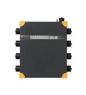
The Fluke 1760 Three-Phase Power Quality Recorder complies strictly with IEC 61000-4-30 Class-A, for advanced power quality analysis and consistent conformity testing. Designed for the analysis of utility and industrial power distribution systems, in medium and low voltage networks, these power quality monitors give customers the flexibility to customize threshold selection, algorithms and measurements. The Fluke 1760 power recorder records the most thorough detail for user-selected parameters.
Usage
Detailed fault analysis – Performs high-speed transient analysis and finds root causes of equipment malfunctions for later mitigation of malfunctions and predictive maintenance. The fast transient option, with a measuring range of 6,000 V, makes it possible to record very short impulses such as lightning strikes.
Class-A Quality of Service Compliance – Validates the quality of incoming power at the service gateway. Thanks to Class A conformance, the Fluke 1760 allows unquestioned verification.
Correlation of events at multiple locations – Using GPS time synchronization, users can quickly detect where a fault first occurred, both inside and outside the facility.
Galvanic separation and DC coupling – Allows complete measurement of dissimilar power systems. For example, troubleshooting a UPS system by simultaneously recording battery voltage and power output.
Power quality and power load monitoring – Assess baseline power quality to validate compatibility with critical systems prior to installation and verify electrical system capacity before increasing loads.
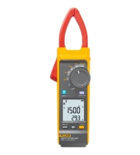
The Fluke 393 FC CAT III 1500 V True-rms Solar Clamp Meter with iFlex is designed for solar photovoltaic (PV) installation technicians and maintenance professionals who work in high voltage DC environments: PV arrays, wind power, electric railways, data centers battery banks for uninterruptible power supplies. The clamp meter will measure up to 1500 V DC and 1000 V AC with test leads, and up to 999.9 A DC or AC through the clamp jaw. The included iFlex flexible current probe extends AC current measurements up to 2500 A. The 393 has a thin jaw, giving you access to cables in crowded combiner boxes. Plus, the test leads are designed with your work in mind, and are also rated to CAT III 1500 V DC.
Key functions of the solar clamp meter:
- IP54 rated, ideal for work outdoors including PV panel testing
- DC power measurement, showing readings in kVA
- Audio Polarity indicator helps prevent accidental miswires
- Visual Continuity provides a bright green light in the display, ideal when working in dark and noisy environments
- Logging and reporting of test results via Fluke Connect software
- When measuring ac current the included iFlex flexible current probe gives you unparalleled access to cable is tight spaces. The iFlex probe can be twisted through extremely small spaces and provide accurate current measurements.
The world's first CAT III 1500 V true-RMS solar clamp meter
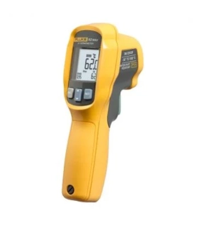
Fluke 62 Max Infrared Thermometer delivers single-laser targeting accuracy
The Fluke 62 MAX Infrared thermometer delivers many of the features of the Fluke 62 MAX+, but features a single laser and 10:1 distance to spot ratio. You can use the Fluke 62 MAX to perform non-contact temperature measurements on transformers, motors, pumps, panels, breakers, compressors, duct, steam lines, valves, and vents. It is small in size and extremely easy to use. The single laser helps you pinpoint the target for more accurate readings and makes it easier to measure temperatures in hard to reach areas. With its IP54 rating for dust and water resistance you can rely the Fluke 62 MAX to deliver accurate, repeatable temperature measurements, rain or shine, in even the dirtiest and dustiest industrial sites. And it’s rugged enough to take a 3-meter drop so no worries even if you work from a ladder.
Other useful features:
- High and low alarms for rapid detection of temperatures outside the limits
- Powered by a single, standard AA battery.
- Comes with a three-year warranty -30-
- Withstands a 3 m (9.8 ft.) drop
- Offers small, lightweight form factor to clip comfortably to your tool belt or belt loop, or easily fit in your tool box
- Features a large, backlit display to make data easier to read, even in dark areas.
- Displays Min/Max/Avg/Dif: the minimum, maximum or average temperature, or the difference between two measurements
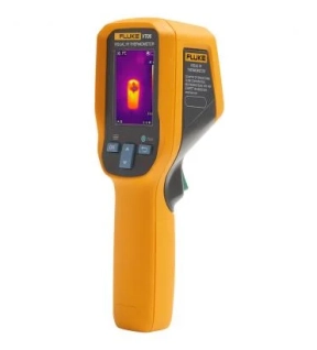
Fluke VT series is built with legendary Fluke ruggedness and quality. With compact design and upgraded function, the temperature measurement is visualized, so that you can obtain a clear and accurate infrared thermal image.