Measuring Tools
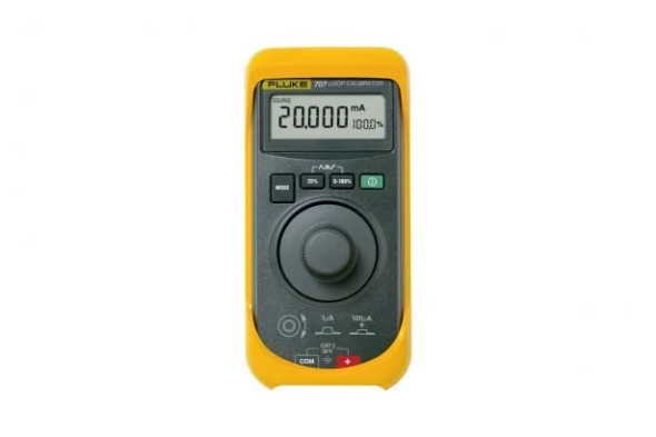
Fluke 707 Current Loop Calibrator with Quick Click Knob
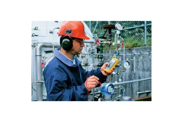
Fastest one-handed handheld tool for loop inspection
The Fluke 707 title="Loop Calibrator">Loop Calibrator is a high performance solution for calibrating, repairing, and maintaining current loops. The new "Quick Click" knob makes the tool extremely fast and easy to operate. The device features:
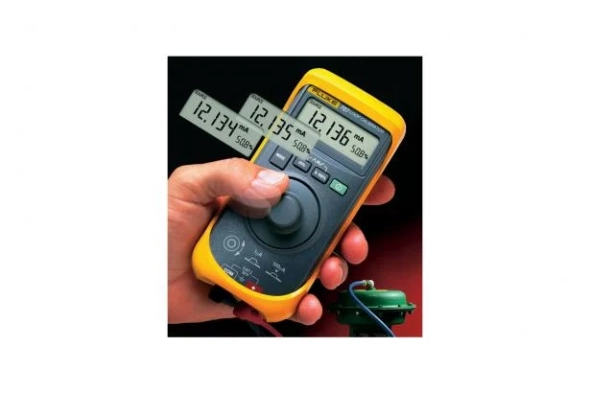
- One-handed user interface with "Quick Click" hold knob
- Source finding, simulation, and mA measurement
- 0.015% accuracy and 0.001 mA resolution
- Simultaneous display of mA and % of range
- Selectable stages or ramp results
- 24 V loop supply with mA measurement, including 250O HART resistor
- 0-28 VDC measurement to check Loop Voltage
- Easy battery replacement without opening the box
- Simple box with separate protective case
- Three year warranty
Download
Produk Lainnya
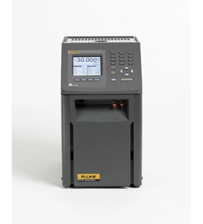
Fluke 9170, 9171, 9172, & 9173 Metrology Well Calibrators
Accurate enough for lab use, and rugged and portable enough to take anywhere
• Best-performing industrial heat sources (accuracy, stability, uniformity) in the world
• Immersion depth to 203 mm (8 in)
• Optional ITS-90 reference input reads PRTs to ±0.006 °C
• Temperature range from –45 °C to 700 °C
Every once in a while, a new product comes around that changes the rules. It happened when we introduced handheld dry-wells. It happened when we introduced Micro-Baths. Now we’ve combined bath-level performance with dry-well functionality and legitimate reference thermometry to create Metrology Wells.
With groundbreaking new proprietary electronics from Fluke Calibration's (patents pending), Metrology Wells let you bring lab-quality performance into whatever field environment you might work in. New analog and digital control techniques provide stability as good as ±0.005 °C. And with dual-zone control, axial (or “vertical") uniformity is as good as ±0.02 °C over a 60 mm (2.36 in) zone. (That’s 60 mm!) Such performance doesn’t exist anywhere else outside of fluid baths.
In short, there are six critical components of performance in an industrial heat source (which the European metrology community explains, for example, in the document EA-10/13): calibrated display accuracy, stability, axial (vertical) uniformity, radial (well-to-well) uniformity, impact from loading, and hysteresis. We added a seventh in the form of a legitimate reference thermometer input and created an entirely new product category: Metrology Wells.
(By the way, Metrology Wells are the only products on the market supported by published specifications addressing every performance category in the EA-10/13. Our specs aren’t just hopes or guidelines. They apply to every Metrology Well we sell.)
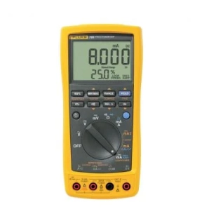
Fluke 789 ProcessMeter™
Double your strength
The Fluke 787 was the first device to combine a DMM and a loop calibrator to give process technicians double the power in one tool. Now even better, range is extended in the Fluke 789 – the ultimate loop calibration multimeter. The Fluke 789 has a 24-Volt supply loop which eliminates the need to take a separate power supply when testing transmitters offline. And with selectable onboard 250-Ohm Hart® resistors, the need to carry separate resistors is eliminated. Now process engineers can do more while carrying far less.
The Fluke 787 was the first device to combine a DMM and a loop calibrator to give process technicians double the power in one tool. Now even better, range is extended in the Fluke 789 – the ultimate loop calibration multimeter. The Fluke 789 has a 24-Volt supply loop which eliminates the need to take a separate power supply when testing transmitters offline. And with selectable onboard 250-Ohm Hart® resistors, the need to carry separate resistors is eliminated. Now process engineers can do more while carrying far less.
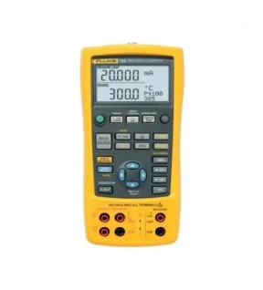
Fluke 726 Precision Multifunction Calibrators
Process calibration designed specifically for process industries
The Fluke 726 is a precise and powerful, yet easy-to-use, field calibrator. It features broad workload coverage, calibration power, and unsurpassed accuracy needed by process professionals. It measures and sources almost all process parameters to calibrate almost anything. Use it to test sensors and valves, and to test and calibrate transmitters. The 726 interprets results without the help of a calculator and stores measurement data for later analysis.
Measurement capabilities
This precision multifunction calibrator measures volts, mA, pressure, RTDs, thermocouples, frequency, and resistance to test sensors and transmitters. The 726 also sources and simulates volts, mA, thermocouples, RTDs, frequency to calibrate transmitters. Measures and/or sources pressure using when paired with any of the 50 Fluke 750P series Pressure Modules to test and calibrate pressure transmitters and other devices. The 726 can also:
- Source mA with simultaneous pressure measurement to conduct valve and I/P test
- Conduct enhanced flowmeter testing with frequency totalizer and frequency pulse train source mode
Designed for ease of use
The 726 has built-in features that make it easier to use in nearly any measurement situation. From its ability to store frequently used test setups, to programming custom RTD probe calibration constants for enhanced temperature measurement, or the integrated voltage input protection design that improves reliability, the 726 is built to perform. The use of two separate channels even allows you to measure, source, or view process signals simultaneously. The backlit display provides better visibility in low-light conditions, and the standard 3-year warranty provides extra confidence that the 726 will be there when you need it to be.
You can also use the 726 to:
- Capture the set, reset, and deadband of a pressure switch with the integrated switch test
- Calculate the transmitter error % to interpret calibration results without the use of a calculator
- Perform fast linearity tests with the auto-step and auto-ramp features
- Power a transmitter during test using 24 V loop supply and simultaneous mA measurement
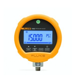
Fluke 700G31 Pressure Gauge Calibrator, -14 to 10,000 psi'
Fluke 700G31 Offers
Compatible with most hydraulic and pneumatic test pumps, users can also make use of Fluke's 700G/TRACK Software to upload over 8000 pressure measurements logged in the field.
Features
- Precision pressure measurement from ±10 inH2O to 10,000 psi (20 to 690 bar)
- Absolute pressure measurement ranges 15, 30, 100, 300 psia
- Accuracy to 0.05% of full scale
- Reference class gauge accuracies to 0.04% of reading
- Easy to use, rugged construction for reliable performance
- CSA; Class 1, Div 2, Groups A-D rating
- ATEX rating: II 3 G Ex nA IIB T6
- Combine with the 700PTPK or 700HTPK pump kits for a complete pressure testing solution for up to 600 psi (40 bar) with the PTP-1 pneumatic pump and up to - - 10,000 psi (690 bar) with the HTP-2 hydraulic pump
- Log up to 8493 pressure measurements to memory (requires 700G/TRACK software)


