Measuring Tools
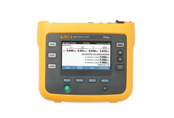
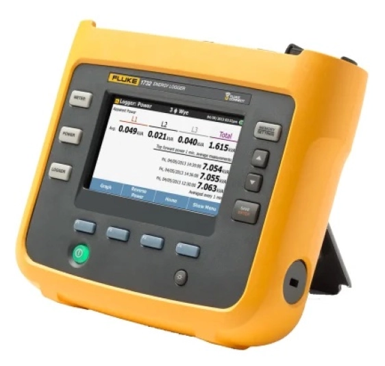
Fluke 1732/INTL Three Phase Power Energy Monitor & Logger, Battery-Powered
Fluke 1732 3 phase Electrical Energy Logger
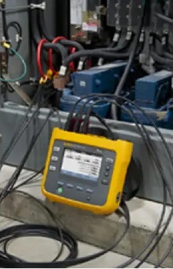
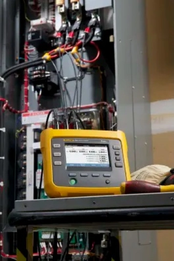
Energy logging is now within your reach—discover where you’re wasting energy, optimize your facility’s energy use and reduce your bill. The new Fluke 1732 Three-Phase Electrical Energy loggers introduce a new simplicity to discovering sources of electrical energy waste. Discover when and where energy in your facility is being consumed; from the service entrance to individual circuits.
Profiling energy usage across your facility helps you identify opportunities for energy savings, and provides you with the data you need to act on them. The new Energy Analyse software package allows you to compare multiple data points over time to build a complete picture of energy usage, which is the first step to reduce the cost of your energy bill.
Features and Benefits
• Key Measurements: Automatically capture and log voltage, current, power, power factor, energy and associated values
• Bright, colour touch screen, perform convenient in-the-field analysis and data checks with full graphical display
• Comprehensive Logging: More than 20 separate logging sessions can be stored on the instruments.
• Optimised User Interface: Quick, guided, graphical setup ensures that you are capturing the right data every time, and the intelligent verification function indicates that correct connections have been made, reducing user uncertainty
• Convenient Instrument Powering: Power instrument directly from the measured circuit
• Highest safety rating in the industry: 600 V CAT IV/1000 V CAT III rated for use at the service entrance and downstream
• Measure all 3 phases with included 3 flexible current probes
• Complete “in-the-field"" setup through the front panel or Fluke Connect: No need to return to the workshop for download and setup or to take a computer to the electrical panel
• Fluke Connect® compatible: View data locally on the instrument, via Fluke Connect mobile app and desktop software or through your facilities’ WiFi infrastructure
• Energy Analyse Plus application software: Download and analyse every detail of energy consumption with our automated reporting
Fluke 1732/B Contents
Energy logger, basic version (excludes current probes), power supply, voltage test leads, alligator clips (4x), soft case, energy analyse plus software, line cords, colour coding set and documentation on USB flash drive
Fluke 1732/INTL Contents
Energy logger, International version (includes current probes), power supply, voltage test leads, alligator clips (4x), 12 in 1500 A flexible current probe (3x), soft case, energy analyse plus software, line cords, colour coding set and documentation on USB flash drive
Note:
CRITICAL SAFETY ALERT - PLEASE READ! Fluke has determined that certain improper use of the test lead set, 3PHVL-1730 or 3PHVL-1735-5M 'Voltage Test Lead, 3-phase + N', included with the 173x Series, 174x Series Power Quality Loggers and 3540FC Power Monitor, may potentially expose users to hazardous conditions, posing the risk of serious personal injury or death.
Download
Produk Lainnya
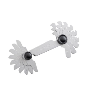
Kennedy 20 BLADE SCREW PITCH GAUGE 60 DEG METRIC
Ideal for accurately measuring internal and external thread forms. Manufactured from hardened and polished steel, the blades are precision milled for optimum accuracy. Enclosed in a steel case.
Featrures and Benefits
• Hardened and polished steel for increased durability
• With precision milled blades for accuracy
• Used to internal and external thread forms
• Enclosed in a steel case for easy storage and portability
Featrures and Benefits
• Hardened and polished steel for increased durability
• With precision milled blades for accuracy
• Used to internal and external thread forms
• Enclosed in a steel case for easy storage and portability
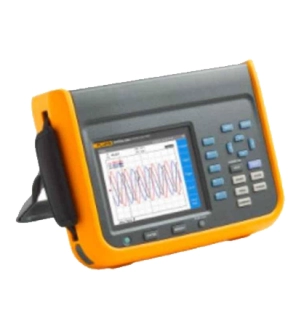
Fluke NORMA 6004/APC 4 Channel Portable Power Analyzer
Fluke NORMA 6004/APC 4 Channel Portable Power Analyzer, 5132974 is a premium quality product from Fluke. Moglix is a well-known ecommerce platform for qualitative range of Power Analysers. All Fluke NORMA 6004/APC 4 Channel Portable Power Analyzer, 5132974 are manufactured by using quality assured material and advanced techniques, which make them up to the standard in this highly challenging field. The materials utilized to manufacture Fluke NORMA 6004/APC 4 Channel Portable Power Analyzer, 5132974, are sourced from the most reliable and official vendors, chosen after performing detailed market surveys. Fluke products are widely acknowledged in the market for their high quality. We are dedicatedly involved in providing an excellent quality array of Fluke Power Analysers.
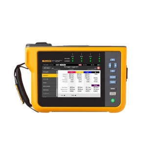
Fluke 1777 - Three-Phase Power Quality Analyzer
Automatic measurements. More flexibility. Better power quality troubleshooting.
Fluke 1770 Series Three-Phase Power Quality Analyzers eliminate the complexities of power quality logging, troubleshooting, and analysis. Engineered to be the faster, easier way to perform power quality studies, the 1770 Series offers automatic measurements, a straightforward user interface and setup, best-in-class specifications, and a simplified reporting platform. The instrument can also be powered directly from the measurement circuit, eliminating the need to find a power outlet or use a lengthy extension cord.
With the 1770 Series you’ll never miss a critical power quality event—from fast transients up to 8 kV, harmonics up to 30 kHz, dips and swells, as well as the voltage, current, and power measurements that enable you to characterize your electrical system.
Automatic measurement capture
Whether you’re performing a quick system check or a detailed power quality study, consistent data is key. The Fluke 1770 Series offers a unique automatic measurement capture system that helps ensure you’re collecting the right data every time, while still giving you the flexibility to select and adjust specific parameters as needed. More than 500 power quality parameters are captured by default and the guided setup makes it easy to select the right parameters for the system you’re working on. Logged data is instantly viewable, downloadable, and shareable with Fluke Energy Analyze Plus software so you never need to wait to finish a session before reviewing results or analyzing data.
Ultimate measurement confidence
The Fluke 1770 Series are 2-in-1 devices that combine the troubleshooting functionality of a power quality meter with the robust analysis and logging capabilities of a standalone power quality analyzer—in a single, easy-to-use, handheld device.
The ‘PQ Meter’ function gives you immediate access to live onscreen data in the field so you can quickly identify potential problems while troubleshooting. The detailed ‘PQ Logging and Analysis’ function eliminates the complexity of performing power quality studies by guiding you through the setup process ensuring you’re capturing the right data every time. Couple these measurement modes with a unique measurement connection autocorrect function and you can be confident that you never need to worry about going back for a second measurement—even if you were unsure about what to look for when you started.
Powerful analysis software with easy-to-create reports
Fluke 1770 Series Power Quality Analyzers come standard with the powerful Fluke Energy Analyze Plus software, designed to eliminate the hassles found with other multi-purpose application software. Energy Analyze Plus helps you evaluate power quality data right out of the box and without extensive training.
Energy Analyze Plus makes downloading, analyzing, tracking, and reporting power quality and energy data easier than ever. Quickly compare results to historical values, benchmark against industry norms, compare measured data to local conditions, and create a more complete picture of what’s occurring across your facility, even as the data is still being collected. Energy Analyze Plus offers unified support for the Fluke 1730, 1740, and 1770 Series of Energy Loggers and Power Quality Analyzers.
“In-workshop” and “in-the-field” setup and download through PC application software
Simple data downloads using USB memory stick, WiFi, LTE, wired Ethernet, or USB cable
Analyze every measured detail of energy consumption and power quality state-of-health with automated reporting
One-touch reporting creates standardized reports conforming to standards like EN 50160, IEEE 519, GOST 33073 IEC 61000-2-2, or export data in PQDIF or NeQual compatible format or CSV for use with third-party software
Advanced analysis allows the user to choose any available logged parameter and create a highly customized view of measurements for advanced data correlation
High-speed voltage transient capture
Transients negatively impact otherwise healthy systems every day and their potential to damage your equipment can’t be underestimated. Whether your system is experiencing impulsive or oscillatory transients, the results can be devastating and cause problems ranging from insulation failures to total equipment failures. The Fluke 1775 and Fluke 1777 incorporate advanced transient capture technology to help you clearly identify high-speed voltage transients, so you have the data you need to stop them in their tracks. The Fluke 1775 Power Quality Analyzer has 1MHz sampling capability to capture fast transients, while the Fluke 1777 Power Quality Analyzer has 20MHz sampling capability to capture the fastest transients in high detail.
Compliant to international standards
The Fluke 1770 Series offers the best-in-class accuracy you’ve come to expect from a Fluke Power Quality Analyzer in a future IEC 61000-4-30 Class A edition 3 compliant package. On top of that, the 1770 Series has been engineered to meet the future requirements of Class A edition, for conformance to EN 50160 and IEEE 519, so you’ll be prepared to tackle tomorrow’s measurement requirements, today.
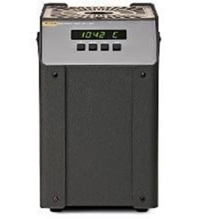
Fluke 9150 Thermocouple Furnace
Low cost thermocouple furnace
• Low-cost thermocouple furnace
• NIST-traceable calibration included
• RS-232 port standard
You told us you weren’t satisfied with the competition’s furnaces for checking industrial thermocouples. You said you wanted something new and more convenient to use—and you wanted it at a lower price than any other furnace available. Well, we’ve got what you asked for, and it’s the Model 9150 Thermocouple Furnace.


