Measuring Tools
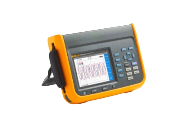
Fluke NORMA 6004/APC 4 Channel Portable Power Analyzer
Fluke NORMA 6004/APC 4 Channel Portable Power Analyzer, 5132974 is a premium quality product from Fluke. Moglix is a well-known ecommerce platform for qualitative range of Power Analysers. All Fluke NORMA 6004/APC 4 Channel Portable Power Analyzer, 5132974 are manufactured by using quality assured material and advanced techniques, which make them up to the standard in this highly challenging field. The materials utilized to manufacture Fluke NORMA 6004/APC 4 Channel Portable Power Analyzer, 5132974, are sourced from the most reliable and official vendors, chosen after performing detailed market surveys. Fluke products are widely acknowledged in the market for their high quality. We are dedicatedly involved in providing an excellent quality array of Fluke Power Analysers.
Download
Produk Lainnya
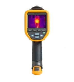
Save time with precise infrared levels and analysis
Whether you're on the roof checking heating, ventilation and air conditioning, deep in the factory checking motors, or if you've locked down the electrical panels, you rely on a tool that has the power and features to do the job quickly.
The Fluke TiS20+ and TiS20+ MAX handheld thermal cameras put the power of thermal imaging at your fingertips. Designed to make your job faster and easier, this thermal imager is the perfect tool for:
- Commercial electrician
- Heating, ventilation, air conditioning and refrigeration technician
- Maintenance technician
Get context with a combination of visual light and infrared images
In thermography, context is important. Let Fluke IR-Fusion™ make your job easier by using a thermal image superimposed on a visual light image to provide a complete picture of where an issue is a problem before it actually becomes a problem. Just slide your finger across the screen to adjust the infrared level. Whether you're experiencing an uneven load on your switchgear or checking your ventilation system, the Fluke TiS20+ helps you quickly detect issues.
You work hard all day, your tools too
You must not let your thermal imager be damaged by the environment. You can sleep well at night knowing that your camera will stand up to whatever the day throws at it.
- 2 meter high drop test
- Waterproof (IP54)
- Dustproof (IP54)
Stop sorting, start analyzing with Fluke Connect Asset Tagging
Avoid long hours on the computer setting up your thermal images, let Asset Tagging do all the work for you. No more dragging and dropping or renaming files in the office, just scan the QR code on your assets, take thermal images and they are automatically sorted by assets. Start spending your time analyzing images and creating reports instead of sorting files one by one.
Longest battery life in a Fluke thermal camera
The TiS20+ and TiS20+ MAX work non-stop, with a battery life of over 5 hours of continuous use making it the longest battery life in a Fluke thermal camera. Save battery power for multiple inspection points with sleep mode. Just press the power button once and you are ready to go.
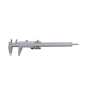
Metric & Inch Reading - Graduation: 0.02mm/0.001"
Incorporating Quadri feature - gives outside, inside, depth and step readings.
Fine adjustment feature allows improved sensitivity of slider movement.
14° vernier face angle reduces parallax.
Satin chrome finish with clear easy read graduations.
Incorporating Quadri feature - gives outside, inside, depth and step readings.
Fine adjustment feature allows improved sensitivity of slider movement.
14° vernier face angle reduces parallax.
Satin chrome finish with clear easy read graduations.
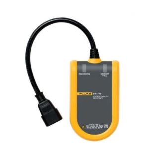
The Fluke VR1710 Power Quality Recorder, is a single-phase plug-in voltage quality recorder that offers an extremely easy-to-use solution for detecting and recording power quality problems, enabling immediate action and minimizing downtime. The VR1710 single-phase recorder meets the needs of maintenance and facilities management personnel in large service, utility, and industrial service organizations where power quality is critical to their business operations. Power quality parameters include average RMS, transients, flicker, and harmonics up to the 32nd recorded using a user-selectable averaging period from 1 second to 20 minutes.
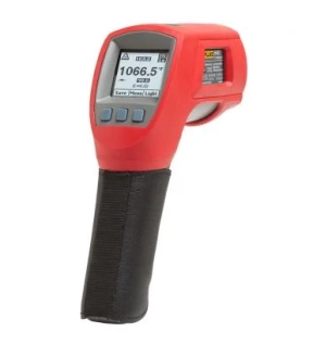
Use the Fluke 568 Ex for intrinsically safe temperature measurements anywhere in the world
The Fluke 568 Ex Intrinsically Safe Infrared Thermometer is certified by major rating bodies for use in Class I Div. 1 and Div. 2 or Zone 1 and 2 hazardous environments anywhere in the world. Whether you work in petroleum, chemical, oil and gas, or pharmaceutical environments, the 568 Ex allows you to carry the most trusted name in test tools into most Ex-rated areas around the globe. The simple, three-button on-screen menu interface is quick to use and makes even complex measurements easy. It takes just a few pushes of a button to adjust emissivity, record data, or turn on and off alarms. The 50:1 distance-to-spot ratio allows you to measure smaller objects from further away. And it also is compatible with K-type probes for contact measurements. Either way, you can count on the rugged, ergonomic design to stand up to tough conditions.
Other useful features:
- Instantly alerts you to measurements outside of set limits with audible and visual alarms
- Provides with 1% measurement accuracy
- Comes with thermocouple K bead probe and two-year warranty -30-
- Features a rugged, easy-to-use, ergonomic design that stands up to tough industrial, electrical, and mechanical environments
- Works with mini-connector K-type thermocouples
- Allows easy access to advanced features with soft-key buttons and graphical display
- Captures up to 99 points of data for quick downloading to a PC through the USB connection
- Powered by two AA batteries
- Allows you to confidently measure a wide variety of surfaces with adjustable emissivity and built-in materials table
- Easily adapts to lighting conditions with a two-level backlight