Measuring Tools
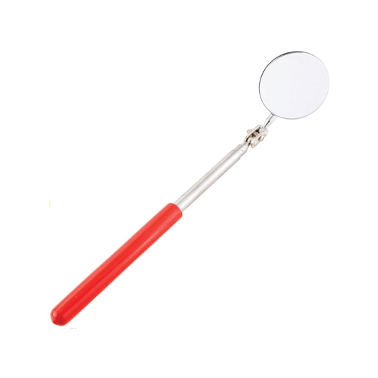
Kennedy ADJ TELESCOPIC 2" DIA INSPECTION MIRROR
The Kennedy range of circular inspection mirrors feature a ball and socket universally positional joint, holding the high grade distortion free mirror at any angle. They come mounted on chrome plated high polish finish telescopic shafts.
Features and Benefits
• Ball and socket universally positional joint for easy positioning
• High grade distortion-free mirror
• Durable chrome plated high polish finish telescopic shafts
Specifications
1.1/4"
• Diameter: 30mm
• Includes high power magnet and pocket clip
• Length Closed/Open (180/480mm)
2"
• Diameter: 50mm
• Length Closed/Open (280/420mm)
Typical Applications
• Inspection
• Automotive
• Engineering
Download
Produk Lainnya
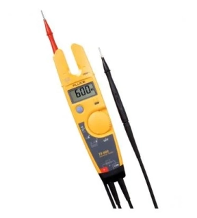
• Measure current up to 100 A without breaking the circuit
• Meter automatically selects AC or DC voltage, up to 600 V
• Resistance measurements up to 1000 Ω plus continuity test
• Work in tight spaces with detachable SlimReach™ probe tips
• Meter automatically selects AC or DC voltage, up to 600 V
• Resistance measurements up to 1000 Ω plus continuity test
• Work in tight spaces with detachable SlimReach™ probe tips

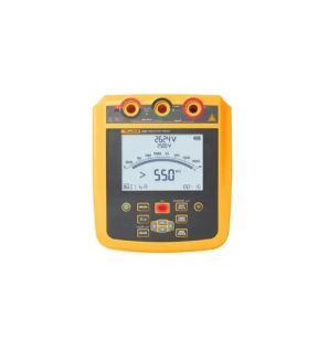
The Fluke 1503 is a great choice for basic residential and commercial electrical insulation testing. This rugged, compact tool fits in the palm of your hand. The 1503 is the same form factor as the Fluke 1507 but with a few less features. You can count on it to handle the most common tests at a most affordable price. Additional features, like the remote probe, reduce the time needed to perform repetitive testing.
Other useful capabilities:
• Measures AC/DC voltage from 0.1 V to 600 V
• Includes auto-discharge of capacitive voltage for added user protection
• Provides lo-ohms earth-bond continuity (200 mA)
• Simplifies repetitive or hard-to-reach testing with the remote test probe
• Saves battery power with auto power off
• Presents results on a large, backlit display
• Features CAT IV 600 V overvoltage category rating
• Comes with remote probe, test leads, test probes, alligator clips, and one-year warranty
• Accepts optional Fluke TPAK magnetic hanging system to free your hands for other work
• Runs on four AA alkaline batteries (NEDA 15 A or IEC LR6) for at least 1000 insulation tests
Key Features
• A rugged, compact insulation resistance tester for residential and commercial electricians
• Performs insulation tests from 0.01 MΩ to 2000 MΩ
• Offers two insulation test voltages: 500 V and 1000 V
• Includes live circuit detection to prevent insulation test if voltage >30 V is detected
• Measures resistance from 0.01 Ω to 20.00 kΩ
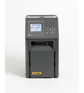
Accurate enough for lab use, and rugged and portable enough to take anywhere
• Best-performing industrial heat sources (accuracy, stability, uniformity) in the world
• Immersion depth to 203 mm (8 in)
• Optional ITS-90 reference input reads PRTs to ±0.006 °C
• Temperature range from –45 °C to 700 °C
Every once in a while, a new product comes around that changes the rules. It happened when we introduced handheld dry-wells. It happened when we introduced Micro-Baths. Now we’ve combined bath-level performance with dry-well functionality and legitimate reference thermometry to create Metrology Wells.
With groundbreaking new proprietary electronics from Fluke Calibration's (patents pending), Metrology Wells let you bring lab-quality performance into whatever field environment you might work in. New analog and digital control techniques provide stability as good as ±0.005 °C. And with dual-zone control, axial (or “vertical") uniformity is as good as ±0.02 °C over a 60 mm (2.36 in) zone. (That’s 60 mm!) Such performance doesn’t exist anywhere else outside of fluid baths.
In short, there are six critical components of performance in an industrial heat source (which the European metrology community explains, for example, in the document EA-10/13): calibrated display accuracy, stability, axial (vertical) uniformity, radial (well-to-well) uniformity, impact from loading, and hysteresis. We added a seventh in the form of a legitimate reference thermometer input and created an entirely new product category: Metrology Wells.
(By the way, Metrology Wells are the only products on the market supported by published specifications addressing every performance category in the EA-10/13. Our specs aren’t just hopes or guidelines. They apply to every Metrology Well we sell.)
The Fluke 1535 and 1537 2,500 V Insulation Resistance Testers are engineered to simplify frontline troubleshooting whether you’re on the factory floor or working in the field at a solar installation. With user selectable test voltages from 250 V to 2,500 V and resistance measurements up to 500 GΩ these testers allow you to cover more workload with a single tool. Equipped with an intuitive user interface, a short circuit current of up to 5 mA and a CAT IV 600 V rating these portable high-voltage insulation testers can deliver rapid and stable resistance measurements no matter where you take them. The 1537 Insulation Resistance Tester also allows you to store measurements for later review or PC transfer, using the provided software.
• Selectable Voltage Tests: Tailor your tests with user-selectable voltages of 250 V, 500 V, 1000 V, and 2500 V to cover both industrial and solar applications.
• Extended Insulation Resistance Measurement: Reach up to 500 GΩ in insulation resistance measurement for a thorough analysis.
• Intelligent Calculations: Automatically calculate Polarization Index (PI) and Dielectric Absorption Ratio (DAR), minimizing the influence of environmental factors.
• High Measurement Capacity: Execute up to 1,300 measurements at 2,500 V or 6,500 measurements at 250 V on a single charge, enhancing productivity.
• Enhanced Safety Features: Benefit from a CAT IV 600V rating and a built-in voltage alarm function for heightened safety during operations.
The Fluke 1537 has these additional features:
• Extended Measurements: The Fluke 1537 enhances your testing capabilities with AC/DC voltage and resistance measurements.
• Stable Resistance Measurements: Achieve faster, more stable insulation resistance measurements with a short circuit current up to 5mA.
• Fine-tunable Test Voltage: Adjust the test voltage from 250 V to 2500 V in 100 V increments to meet specific testing requirements.
• Dielectric Discharge Rate Calculation: Automatically calculate the dielectric discharge rate (DD) to aid in identifying elusive insulation issues.
• Ramp Test Mode: Linearly increase the applied test voltage 100 V/s to help identify potentially hard to identify fault conditions.
• Visual and Audio Continuity Indicator: Verify continuity visually on the screen display or with the audible indicator so you can focus on your testing procedure without looking at the display.
• Customizable Testing Parameters: Set user-defined labels, adjust test duration, and store measurement results for a tailored testing experience.
• Effortless Data Management: Download and manage data effortlessly with the provided PC software.
• Extended Warranty: Enjoy peace of mind with an extended 3-year warranty.
Key Features
• User-selectable voltages of 250 V-2500 V
• Up to 500 GΩ insulation resistance measurement
• Short circuit current up to 5mA for fast, stable measurements
• Automatically calculate PI and DAR
• Perform 1,300+ insulation tests on a single charge