Measuring Tools
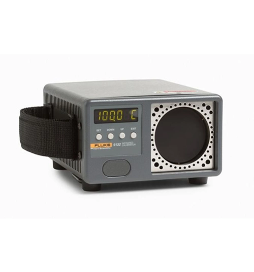
Fluke 9132 and 9133 Portable Infrared Calibrators
Precision when you need it for infrared temperature calibration
Fluke 9132 and Fluke 9133 Portable Infrared Calibrators features:
• Certify IR pyrometers from –30 °C to 500 °C (–22 °F to 932 °F)
• Large 57 mm (2.25 in) blackbody target
• RTD reference well for contact temperature measurement
• Small, compact design in a blackbody calibrator
Whether you’re using in-line or handheld infrared pyrometers, you need good calibration standards to verify their accuracy. Our portable IR calibrators provide stable blackbody targets for calibrating noncontact IR thermometers from –30 °C to 500 °C.
These blackbody calibrator units feature a temperature controlled measurement surface with a diameter of 2.25 in (57 mm). The target temperature can be controlled in set-point increments of 0.1° from –30 °C to 500 °C and a well is located directly behind the blackbody surface for contact temperature measurement.
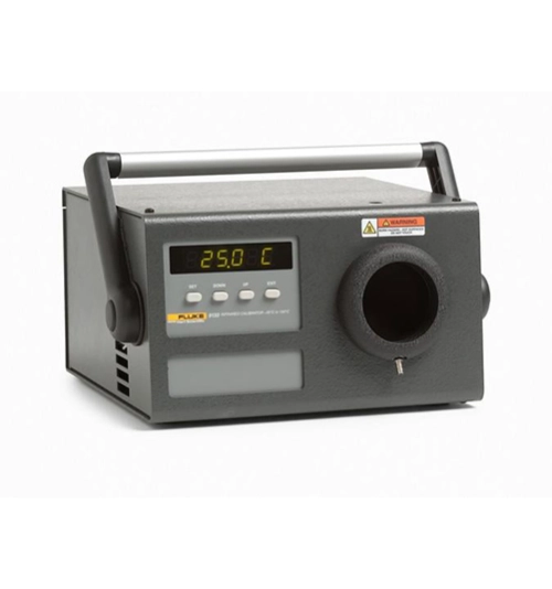
Download
Produk Lainnya
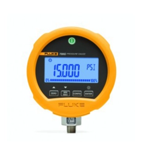
Fluke 700G31 Offers
Compatible with most hydraulic and pneumatic test pumps, users can also make use of Fluke's 700G/TRACK Software to upload over 8000 pressure measurements logged in the field.
Features
- Precision pressure measurement from ±10 inH2O to 10,000 psi (20 to 690 bar)
- Absolute pressure measurement ranges 15, 30, 100, 300 psia
- Accuracy to 0.05% of full scale
- Reference class gauge accuracies to 0.04% of reading
- Easy to use, rugged construction for reliable performance
- CSA; Class 1, Div 2, Groups A-D rating
- ATEX rating: II 3 G Ex nA IIB T6
- Combine with the 700PTPK or 700HTPK pump kits for a complete pressure testing solution for up to 600 psi (40 bar) with the PTP-1 pneumatic pump and up to - - 10,000 psi (690 bar) with the HTP-2 hydraulic pump
- Log up to 8493 pressure measurements to memory (requires 700G/TRACK software)
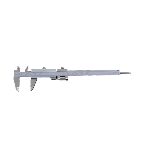
Metric & Inch Reading - Graduation: 0.02mm/0.001"
Incorporating Quadri feature - gives outside, inside, depth and step readings.
Fine adjustment feature allows improved sensitivity of slider movement.
14° vernier face angle reduces parallax.
Satin chrome finish with clear easy read graduations.
Incorporating Quadri feature - gives outside, inside, depth and step readings.
Fine adjustment feature allows improved sensitivity of slider movement.
14° vernier face angle reduces parallax.
Satin chrome finish with clear easy read graduations.
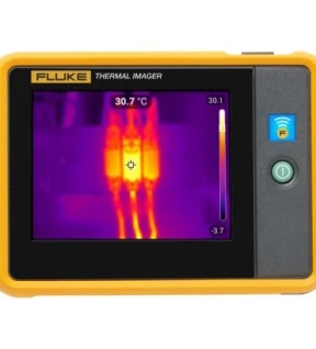
Portable thermal camera for industrial inspection
In the right place. At the right time. With the right tools.
The bigger the problem, the faster you have to solve it. The new pocket-sized Fluke Thermal Imager gives you the ability to minimize downtime in everyone's hands. It's the first line of defense for easy troubleshooting. Stop solving problems after they happen, start preventing them.
This tool is used because it is reliable when doing its job.
A camera that's small enough to carry around every day without worry. Always ready to use. Resistant to dirt and water. Able to survive even if it falls from a height of up to 1 meter. Now a powerful infrared probe is in your pocket for fast temperature scanning of electrical equipment, machinery and other assets.
Automatically saves your thermal images in the correct folder.
With Fluke Connect Asset Tagging, you eliminate the tedium of sorting and organizing your infrared images. Simply by scanning the QR code or asset barcode, your infrared image and all information with date and time will be saved to the specified folder. Send via Wifi or automatically upload once connected to a network or computer via USB. It's about timing. Now you can save, find, and report issues more efficiently before they become problems.
Get the infrared level you want every time.
The 3.5” LCD touch screen offers IR-Fusion™ to combine visual images with infrared images to make it easier to locate problems. Just slide your finger across the screen to adjust the settings.
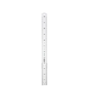
Our Kennedy® rigid steel rulers are made from the finest quality spring-tempered stainless steel and finished in satin chrome. They're flexible and durable with an anti-glare finish for use in any environment.
Features and Benefits
• Anti-glare finish for easy reading in all lighting levels
• Permanent black figures and graduations allow for precise measurements
• Round end complete with hanging hole for easy storage
• Anti-rust for product longevity
Standards
• BS 4372:1968
Features and Benefits
• Anti-glare finish for easy reading in all lighting levels
• Permanent black figures and graduations allow for precise measurements
• Round end complete with hanging hole for easy storage
• Anti-rust for product longevity
Standards
• BS 4372:1968